This common problem has a great fix on www.WJJeeps.com the Jeep Grand Cherokee site:
Click here to be directed to that site!
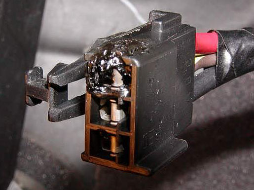
Blower motor connector repair
(AZC Blower motor inoperative or intermittent operation)
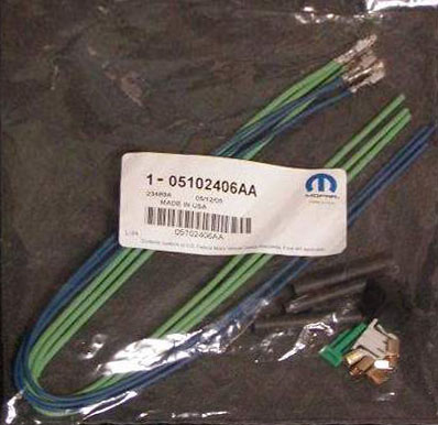
This is a common failure on 1999-2004 WJ models with the AZC (Automatic Zone Control) system. The connector on the blower motor control module overheats, resulting in intermittent or no operation of the blower motor. Mopar released a connector harness repair kit to fix the problem. The damaged connector is cut off and new wires are spliced into place. Only the green wires from the kit are used. One end of each of the 3 green wires goes into the new connector end that is provided. When inserting the wires into the connector, the locking spring tabs should be on the bottom. There is a gray plastic retainer that is then installed around the three wires that were just inserted into the connector.
The part number for the kit is 05102406AA and the MSRP is $17.85.
Blower motor wiring repair kit # 05102406AA
** Update: New and improved parts are available for this repair **
The new resistor is p/n 5179985AA (MSRP $77.95).
Wiring kit (with mounting plate) p/n 68052436AA is also required (MSRP $29.80).
The cause for this failure may be the motor, or blower wheel assembly. Debris from the environment may attach to the wheel causing additional weight, and drag on the motor. If the motor is worn from age, the effort to operate the motor could cause high current draw. Verify current draw with an amperage meter. Amp draw should be approx (13-17) amps when blower is operating on high mode
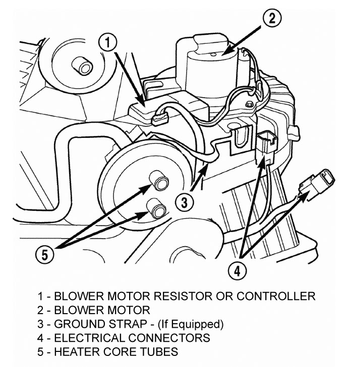
Blower motor control module location (below glovebox)
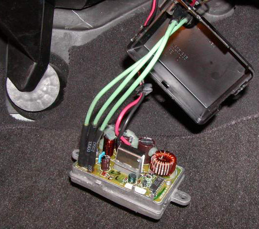
Alternative repair method
Some owners have elected to repair the wiring by soldering wire splices directly to the terminals inside the blower motor control box and not using a connector.
Direct wiring repair
--------------------------------------------------------------------------------
Additional blower motor information and diagnostics
Blower motor resistor block / blower motor controller
- Manual temperature control system
Models with the standard manual temperature control system have a BLOWER MOTOR RESISTOR. The blower motor resistor is mounted to the bottom of the HVAC housing, under the instrument panel and just inboard of the blower motor. It can be accessed for service without removing any other components.
The resistor has multiple resistor wires, each of which will reduce the current flow to the blower motor to change the blower motor speed by changing the resistance in the blower motor ground path. The blower motor switch directs the ground path through the correct resistor wire to obtain the selected speed.
With the blower motor switch in the lowest speed position, the ground path for the motor is applied through all of the resistor wires. Each higher speed selected with the blower motor switch applies the blower motor ground path through fewer of the resistor wires, increasing the blower motor speed. When the blower motor switch is in the highest speed position, the blower motor resistor is bypassed and the blower motor receives a direct path to ground.
The blower motor resistor block cannot be repaired and, if faulty or damaged, it must be replaced.
AZC (Automatic Zone Control) system
Models equipped with the optional Automatic Zone Control (AZC) system have a BLOWER MOTOR CONTROLLER. The controller allows the selection of almost infinitely variable blower motor speeds. The controller is mounted to the HVAC housing, under the instrument panel and just inboard of the blower motor, in the same location used for the blower motor resistor on manual temperature control systems. It can be accessed without removing any other components.
The blower motor controller output to the blower motor can be adjusted by the blower motor speed switch knob on the AZC A/C Heater control panel, or it can be adjusted automatically by the logic circuitry and programming of the AZC control module. In either case, the AZC control module sends the correct pulse width modulated signal to the blower motor controller to obtain the selected or programmed blower motor speed.
The blower motor controller cannot be repaired and, if faulty or damaged, it must be replaced.
--------------------------------------------------------------------------------
Blower motor switch - description
The A/C Heater blower motor is controlled by a rotary-type blower motor switch, mounted in the A/C Heater control panel. On vehicles with manual temperature control systems, the switch allows the selection of four blower motor speeds, but will only operate with the ignition switch in the On position and the A/C Heater mode control switch in any position, except Off. On vehicles with the Automatic Zone Control (AZC) systems, the switch allows the selection of Lo Auto, Hi Auto, and ten speed settings between Lo and Hi.
On manual temperature control systems, the blower motor switch is connected in series with the blower motor ground path through the a/c heater mode control switch. The blower motor switch directs this ground path to the blower motor through the blower motor resistor wires, or directly to the blower motor, as required to achieve the selected blower motor speed.
On AZC systems, the blower motor switch is just one of many inputs to the AZC control module. In the manual blower modes, the AZC control module adjusts the blower motor speed through the blower motor controller as required to achieve the selected blower switch position. In the auto blower modes, the AZC control assembly is programmed to select and adjust the blower motor speed through the blower motor controller as required to achieve and maintain the selected comfort level.
The blower motor switch cannot be repaired and, if faulty or damaged, it must be replaced. The switch is serviced only as a part of the a/c heater control assembly.


 Reply With Quote